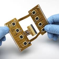
PCB Flex Circuits
Often PCB flex circuits are required to handle harsh environments. Temperature, chemicals, moisture and shock & vibration are just some of the challenges that these circuits may have to face. To overcome these issues, a number of techniques need to be used to ensure that the flex circuit can work as intended. One of these techniques is proper grounding.
A poorly designed ground will put your entire device at risk of EMI and other issues. To avoid this, you need to understand how current travels on a flex circuit and what causes ground loops.
To prevent a ground loop, you should make sure that your traces do not touch each other and that your copper is arranged properly. You should also take care to use a good quality copper and to keep track of the materials you are using. For example, if you are designing a pcb flex that will be constantly creasing and moving, it is best to use Rolled Annealed copper (RA). This type of copper can stretch longer before fatigue cracking occurs compared to unannealed copper. It is also springier in the Z deflection direction which can help with your bending and movement needs.
How to Ensure Proper Grounding in PCB Flex Circuits
If you are working with a high-speed design, you will need to consider how your signal will propagate on the ground plane and if it is going through any gaps or voids. These can cause impedance discontinuities that can lead to EMI issues. To minimize this, you can use techniques such as stitching vias to the ground plane and using a tighter mesh on the ground plane.
You should also be careful when routing high-speed signals and make sure that you are following all of the rules for placing high speed components. This will include ensuring that you are following the signal paths, leaving escape vias and dense bus routing between parts. You should also be careful not to inadvertently allow the traces to pass over a ground plane split or via stub. These can all be a source of EMI and signal degradation.
The versatility of PCB flex is evidenced by its widespread adoption across diverse industries. In consumer electronics, flexible circuits are used in smartphones, tablets, and wearables to enable compact designs and innovative form factors. In automotive applications, PCB flex is employed in vehicle infotainment systems, dashboard displays, and advanced driver assistance systems (ADAS), where space is limited, and durability is essential.
With the right tools and knowledge, you can create a flexible printed circuit board that will meet your exact specifications and requirements. You can use the full set of CAD features and automated drawing tools in Draftsman in Altium Designer to design your flex circuits quickly and easily. To get started, download a free trial of Altium Designer today. This powerful, feature-rich tool is part of the Altium 365 platform and provides everything you need to design advanced electronics.